
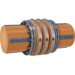
Belts & pipes covers pipe throughput, the head-lift table and the basic sloshing rules. This page goes one level deeper into how head lift actually propagates through a network and into the two buildings that start every fluid chain: the Water Extractor and the Packager.
Water Extractor
The  Water Extractor is unlocked with Tier 3 – Coal Power and outputs 120 m³/min at 100% (up to 300 m³/min at 250% clock), drawing 20 MW (67.2 MW at 250%). It needs at least 9 m of water depth – many rivers are too shallow – and a 25 × 25 m footprint; unlike ore nodes, water tiles are unlimited and carry no purity rating. If you'd rather not place one in a lake, Water Resource Wells (8 wells, up to 55 satellite extractors, up to 13 125 m³/min combined) and the by-product water from recipes such as Aluminum Scrap or Non-Fissile Uranium are alternative sources.
Packager
The Packager (10 MW, one belt and one pipe connection each way, 10 m head lift, Tier 5 – Fluid Packaging) converts a fluid into a solid item you can put on a belt or in a train, and back again. Standard Package/Unpackage recipes run at 60 m³/min (Water packages at 2 m³ per 2 s); it handles Water, Oil, Heavy Oil Residue, Fuel, Turbofuel, Rocket Fuel, Ionized Fuel, Liquid Biofuel, Alumina Solution, Sulfuric Acid, Nitric Acid and Nitrogen Gas. Empty Canisters (liquids) and Empty Fluid Tanks (gases) are returned on unpackaging, so a canister loop over a belt keeps the packaging line self-sufficient.
How head lift really propagates
Head lift is not a network-wide value – it is tracked per filled pipe segment, and a few rules explain behaviour that otherwise looks like a bug:
- Junctions split head lift, not flow. A Pipeline Junction gives every output the full head lift of its input; only the flow rate divides between the open outputs. A Junction merging several inputs instead takes the highest head lift among its sources for the whole downstream network – in principle a single elevated, full Fluid Buffer can "lift" several unpumped Water Extractors below it, though this is closer to an exploit than intended design. A Junction Cross has no flow limit of its own (two Mk.2 inputs can merge into 1 200 m³/min), so exceeding 300 m³/min out of extractors needs Mk.2 pipe regardless of the junction.
- Pumps reset head lift, they don't add it. A second pump placed within the first pump's head-lift range doesn't stack on top of it – it resets the pressure to its own 20 m (Mk.1) or 50 m (Mk.2) measured from its own position. An unpowered pump still passes fluid one-way but with 0 m of head lift, acting as a plain check valve.
- Segments need head lift equal to their vertical rise, and only fully-filled segments pass pressure onward at all. Just above a building's "actual" head-lift figure, flow collapses abruptly; about 2 m further it stops completely. Head lift is independent of flow rate, and gases ignore it entirely.
- Pumps, valves and junctions sitting directly on a pipe (not on a support) can cost roughly 1 m³/min of throughput to the small piece of pipe inside the fitting itself.
| Source | Head lift |
|---|---|
| Water Extractor, Oil Extractor, Resource Well Extractor | 10 m |
| Refinery, Blender, Packager output | 10 m |
| Fluid Buffer (full) | 8 m (proportional when partially filled) |
| Industrial Fluid Buffer (full) | 12 m (proportional) |
| Pipeline Pump Mk.1 | 20 m (up to ≈ 22–23 m in practice), 4 MW |
| Pipeline Pump Mk.2 | 50 m (up to ≈ 55–57 m in practice), 8 MW |
Valves
A Valve limits flow to anywhere from 0.0 to 600.0 m³/min in 0.1 steps and only lets fluid through in one direction, like an adjustable check valve. Unlike a pump, a Valve does not block head lift even when its flow limit is set to 0 – it only throttles throughput, and lets more through when the pressure behind it is higher. Typical uses: stopping backflow in a manifold, prioritising one consumer (for example water to a power plant) ahead of side uses, or deliberately throttling a by-product line.
Reading a pipe: the Flow Indicator
Any straight pipe segment of 6 m or more shows a Flow Indicator: the tint identifies which fluid is inside, the spacing between rings shows how full the pipe is, and a pulse once per second shows flow direction and roughly how fast it's moving. "Clean" pipe variants sold in the AWESOME Shop skip the indicator for a plainer look. A pipe mixing two different fluids blocks entirely until flushed (per segment, or the whole network) from the pipe or pump's context menu – so a manifold should only ever carry one fluid end to end.