
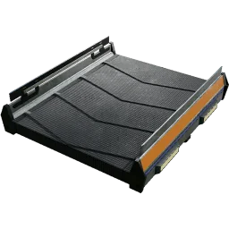
Conveyor belts
| Tier | Items/min | m/s | Factor vs. previous | Build cost per segment (up to 56 m: ≈ 0.5 per m) | Unlock |
|---|---|---|---|---|---|
 Mk.1 Mk.1 |
60 | 1.2 | – | Iron Plate | Tier 0 – HUB Upgrade 4 |
 Mk.2 Mk.2 |
120 | 2.4 | ×2 | Reinforced Iron Plate | Tier 2 – Logistics Mk.2 |
 Mk.3 Mk.3 |
270 | 5.4 | ×2.25 | Steel Beam | Tier 4 – Logistics Mk.3 |
 Mk.4 Mk.4 |
480 | 9.6 | ×1.78 | Encased Industrial Beam | Tier 5 – Logistics Mk.4 |
 Mk.5 Mk.5 |
780 | 15.6 | ×1.625 | Alclad Aluminum Sheet | Tier 7 – Logistics Mk.5 |
 Mk.6 Mk.6 |
1 200 | 24 | ×1.54 | Ficsite Trigon + Time Crystal | Tier 9 – Peak Efficiency |
- Segment 0.5–56 m (7 foundations), minimum curve radius 2 m, maximum slope 35°; no climbing and curving at the same time. The first snap point is the input, the second the output; the direction cannot be reversed afterwards, but the tier can be upgraded or downgraded in place (material difference is charged).
- Items stop at the end of a belt (they do not fall off); no stacks on belts. Belts pull from a building's output slot and push into its input slot if the item is accepted.
- Belts move standing players at belt speed (Mk.6 24 m/s = 86.4 km/h); running with Blade Runners on a Mk.6 reaches 135 km/h.
- Belts that pass through buildings must be built after the buildings (“Encroaching other's clearance”).
Lifts
Same throughput as the belt of the same tier; cost 2× the material (≈ 1 per m); height 4–48 m per lift in 1 m steps, chainable; unlimited between two Conveyor Lift Floor Holes. Since 1.1 splitters and mergers attach to the input, output and any intermediate point of a lift.
Splitters and mergers
| Building | In / out | Internal buffer | Unlock |
|---|---|---|---|
| Conveyor Splitter | 1 → up to 3 | 9 items | Tier 1 – Logistics |
| Conveyor Merger | up to 3 → 1 | 1 item | Tier 1 – Logistics |
 Smart Splitter Smart Splitter |
1 → 3 with 1 rule each | 9 (2 held back with an Overflow rule) | MAM Caterium – Smart Splitter (10 AI Limiter, 50 Reinforced Iron Plate) |
| Programmable Splitter | 1 → 3 with several rules, max. 64 in total | 9 | MAM Caterium – Programmable Splitter (100 AI Limiter, 50 Computer, 50 Heavy Modular Frame) |
| Priority Merger (1.1) | 3 → 1 with low/medium/high priority per input | 1 | MAM Quartz – Material Resonance Screening (15 Crystal Oscillator, 100 Reinforced Iron Plate) |
- Splitters distribute round-robin; blocked outputs are skipped (nothing is lost) → exactly 1:n when nothing blocks. Internal processing 2 000/min (more than a Mk.6). Splitters and mergers cannot attach directly to building ports, but to both ends of a lift and onto existing straight belts; stackable in 2 m steps.
- Smart Splitter rules: Any, None, Any Undefined (only items without their own rule), Overflow (only when no other output can take the item; several overflow outputs share evenly), or a specific item. Programmable Splitters allow several items per output but no ratio splits. Typical uses: overflow → AWESOME Sink, sorting mixed (“sushi”) belts, pressure relief in belt loops.
- A Merger takes round-robin from all occupied inputs; the belt tier is irrelevant. A Priority Merger serves the highest occupied priority exclusively (e.g. local 400/min before an 80/min import).
Manifold vs. balancer
- Manifold (splitters in a row): compact and extensible; front machines fill first, the rear ones wait; after the settling time all run at 100 % as long as supply ≥ demand and the belt has capacity. Calculate the fill time in advance or speed it up with a Somersloop or overclock.
- Load balancer (exact 1:n): nest splitters; 1:2^a·3^b directly (2, 3, 4, 6, 8, 9, 12, 18, 24, 27 …); other values by looping one output back (1:5 from 1:6, 1:7 from 1:8, 1:11 from 1:12, 1:13 from 1:16 with 3 outputs back, 1:17 from 1:18; 1:10 = 2 × 1:5, 1:14 = 2 × 1:7, 1:15 = 1:5 → 1:3). Loopbacks cost belt capacity.
- Belt balancer (n:m): interleave several load balancers; always split first, then merge, and never exceed the capacity of a belt section. Examples 2:2, 3:3, 4:4 = 2:2 flat → 2:2 vertical → 2:2 flat; 6:6 = 3:3 → 2:2; 9:9 = 3:3 → 3:3 → 3:3.
- Recommendation: avoid balancers (space); use manifolds, modular builds (make Screws and Quickwire on site) and 1:1 pairings. See Building ratios & manifolds.
Storage as buffer
Storage Container 24 slots (1 in / 1 out, 5 × 11 × 4 m), Industrial Storage Container 48 slots (2 in / 2 out, 5 × 11 × 8 m); stackable, ladders on the side; output is LIFO; the Industrial container prefers the output belt built first (no balancing). Containers do not limit throughput.
Pipes
Fluids are measured in m³; recipes and extractors in m³/min (raw game data in litres: 1 000 L = 1 m³). Fluids cannot be sunk and cannot travel on belts or in solid freight cars – only through pipes, Fluid Freight Cars (2 400 m³ since 1.2), packaged (Packager) or as packaged items by drone or truck.
| Building | Key figure | Power (MW) | Unlock |
|---|---|---|---|
 Pipeline Mk.1 Pipeline Mk.1 |
300 m³/min | – | Tier 3 – Coal Power |
 Pipeline Mk.2 Pipeline Mk.2 |
600 m³/min | – | Tier 6 – Pipeline Engineering Mk.2 |
 Pipeline Pump Mk.1 Pipeline Pump Mk.1 |
head lift 20 m (real ≈ 22 m) | 4 | Tier 3 – Coal Power |
 Pipeline Pump Mk.2 Pipeline Pump Mk.2 |
head lift 50 m (real ≈ 55 m) | 8 | Tier 6 – Pipeline Engineering Mk.2 |
| Fluid Buffer | 400 m³, head lift 8 m when full | – | Tier 3 – Coal Power |
| Industrial Fluid Buffer | 2 400 m³, head lift 12 m when full | – | Tier 5 – Petroleum Power |
| Valve | flow 0–600 m³/min adjustable, one-way | – | Tier 5 – Oil Processing |
| Pipeline Junction / T-Junction (1.2) | 4 / 3 connections | – | Tier 3 – Coal Power |
Pipes hold about 1.3 m³ per metre (wiki: 1.327 m³/m). A horizontal pipe needs ≈ 1.2–1.5 m of head lift to fill completely. A junction splits evenly between open outputs; backflow is normal.
Head lift
Head lift is the height in metres that a source can push fluid up, measured from the top of the source or pump. A pipe higher than source + head lift → no flow. Downhill and horizontal flow needs no pump; horizontal length is unlimited as long as the throughput limit is not reached.
| Building | Recommended (m) | Actual (m) | Maximum (m) |
|---|---|---|---|
| Pipeline Pump Mk.1 (4 MW) | 20 | 22 | 23 |
| Pipeline Pump Mk.2 (8 MW) | 50 | 55 | 57 |
| Water Extractor, Oil Extractor | 10 | 12 | 13 |
| Refinery, Packager, Blender, Resource Well Extractor | 10 | 11 | 13 |
| Fluid Buffer / Industrial Fluid Buffer (full) | 8 / 12 | 8 / 12 | 8 / 12 |
| Fluid Freight Platform (lower / upper) | 10 | 11 | 13 |
- Head lift does not add up between pumps in series: the second pump must sit within the head lift of the first and then provides its own head lift from its position (spacing ≤ 20 m or 50 m of height). Pumps reset head lift to 20/50 m even with a higher upstream pressure; an unpowered pump acts as a check valve with 0 m.
- Head lift is only passed on through completely filled segments; a segment needs head lift equal to its vertical length. Above the “actual” value the flow collapses abruptly, ≈ 2 m higher it is zero. Head lift is independent of flow; gases ignore it.
- Junctions: a split gives every output the full head lift of the input (only the flow is divided); a merge adopts the highest head lift of all sources for the whole network (a filled Fluid Buffer placed high up “lifts” low Water Extractors without pumps). A junction has no flow limit (2 × Mk.2 in → 1 200 m³/min) but cannot sit directly on building ports.
- Pumps and valves are check valves (flow only in the arrow direction). A valve does not block head lift (even at limit 0). Pumps, valves and junctions placed directly on pipes can cost ≈ 1 m³/min.
Sloshing and manifold rules
- Never plan a pipe manifold above capacity: total demand ≤ 300 (Mk.1) or 600 (Mk.2) m³/min and supply ≥ demand; ideally slightly over-supplied (e.g. 3 Water Extractors = 360 for 8 Coal Generators = 360 → better 2 pipes with 4 generators each, or Mk.2).
- Fill the manifold completely before starting production (pause consumers or use a valve), otherwise the rear consumers starve permanently.
- Place junctions to avoid dead ends; backflow (“sloshing”) in dead ends is normal but can briefly under-supply consumers → a buffer or valve in front of sensitive consumers (power plants).
- Full fluid outputs stop a machine (deadlock). By-products (Heavy Oil Residue, Water from Aluminum Scrap, Dark Matter Residue) must always be removed: further processing, Packager + Sink, or a loop with a valve.
- One pipe carries one fluid; mixing blocks the pipe (reset with “Flush”).
- Return water (e.g. Aluminum Scrap returns 120 m³ Water per 240 Alumina) via valve + merge into the supply; the valve prevents backflow into the Refinery.
- A manifold with many junctions can back up at the end although no segment is saturated (Mk.2 practically < 450 m³/min) → split the supply and feed from both ends (loopback). Prioritise consumers by placing the important ones directly and the others behind a 10 m riser.
Typical fluid ratios
| Chain | Ratio |
|---|---|
| Coal power | 3 Water Extractors : 8 Coal Generators (360 m³/min) |
| Nuclear | 2 Water Extractors : 1 Nuclear Power Plant (240 m³/min) |
| Alumina Solution (Refinery) | 1 Refinery needs 180 m³/min Water + 120 Bauxite → 120 m³ Alumina + 50 Silica; 1.5 Water Extractors per Refinery |
| Aluminum Scrap | 240 m³ Alumina/min per Refinery (= 2 Alumina Refineries) + 120 Coal → 360 Scrap + 120 m³ Water back |
| Fuel | 1 Refinery Fuel (60 m³ Crude → 40 m³ Fuel) : 2 Fuel Generators |
| Plastic / Rubber | 30 m³ Crude/min each → 20 pieces + 10/20 m³ Heavy Oil Residue |
| Pipe Mk.1 (300) | 2.5 Water Extractors, 5 impure / 2.5 normal / 1.25 pure Oil Extractors, 6.67 Coal Generators |
| Pipe Mk.2 (600) | 5 Water Extractors, 1 pure Oil Extractor at 250 %, 2.5 Nuclear Power Plants |
The 15 fluids: liquids Water, Crude Oil, Heavy Oil Residue, Fuel, Turbofuel, Liquid Biofuel, Alumina Solution, Sulfuric Acid, Dissolved Silica (not packageable), Nitric Acid; gases (no head lift, no pumps) Nitrogen Gas, Rocket Fuel, Ionized Fuel, Excited Photonic Matter and Dark Matter Residue (not packageable). Packaged Nitrogen Gas compresses 4×, Packaged Rocket/Ionized Fuel 2× for train or drone transport.
In this planner, click an edge in the factory graph to open the Transport panel – it shows how many belts or pipes of which tier the flow needs (Using SatisfactoryBase).